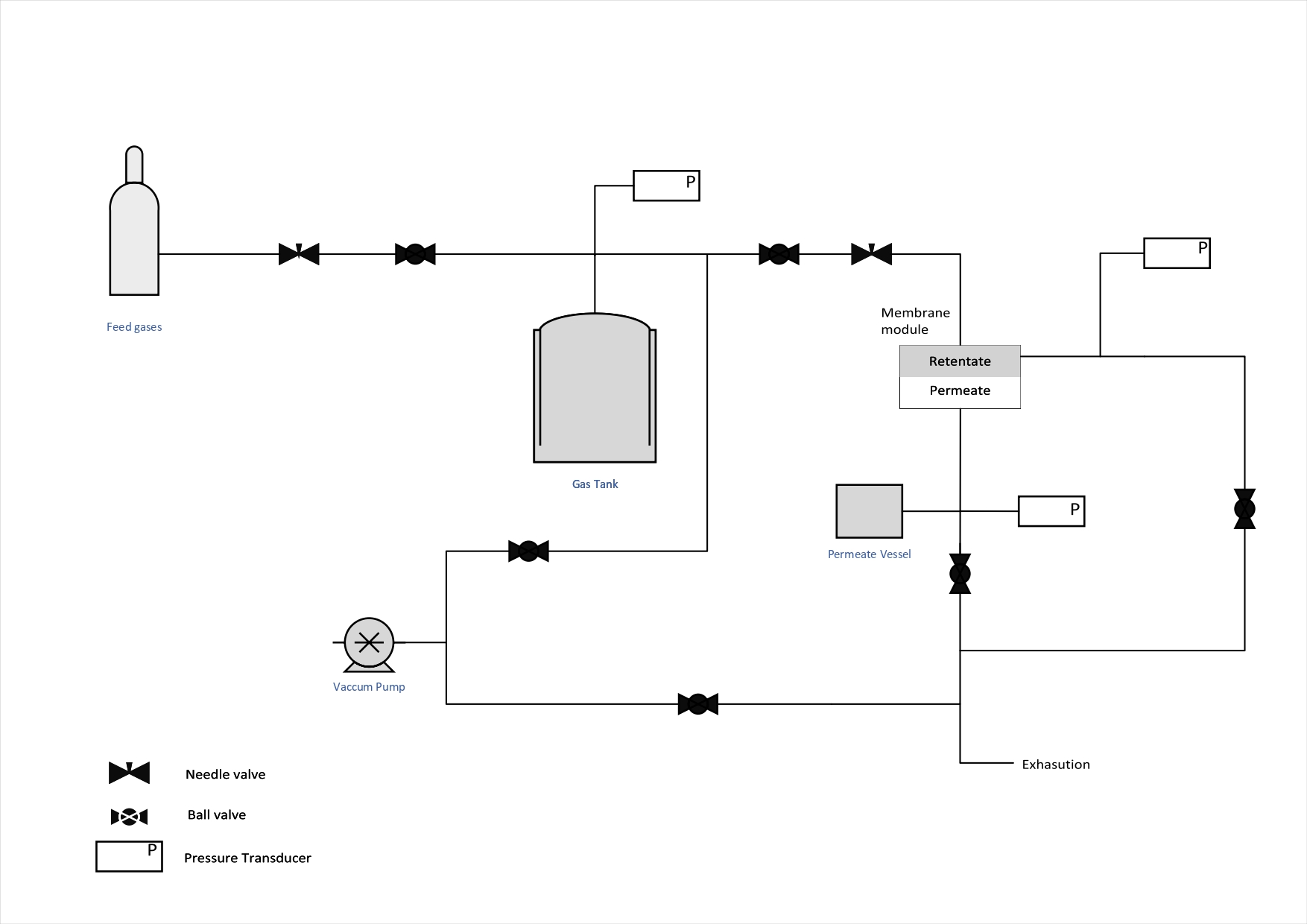
Single gas (mono-component) permeation experiments are performed at 25 ºC (inside a thermostatic chamber) in a home-made permeation set-up, as shown in Figure 1.
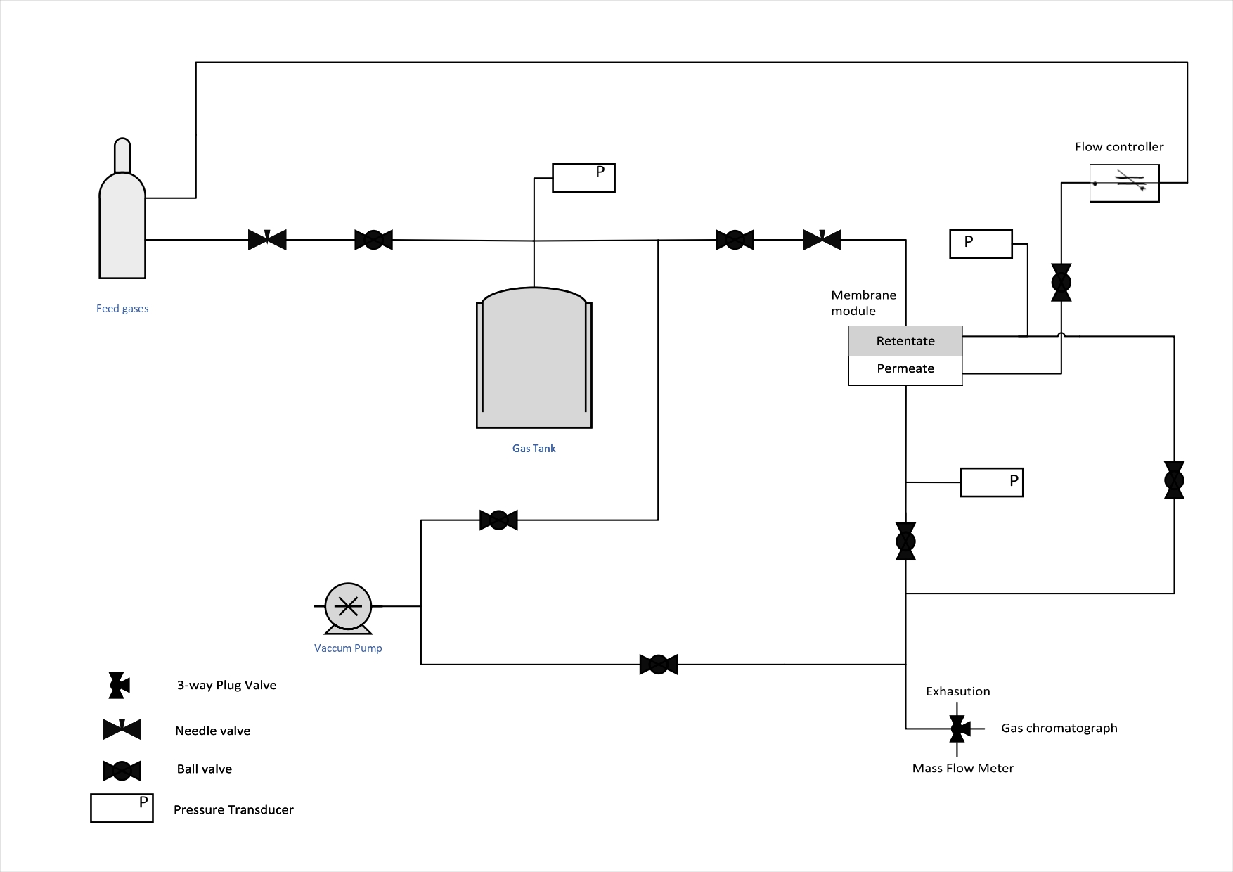
Mixed gas (multi-component) permeation experiments are performed at 25 ºC (inside a thermostatic chamber) in a home-made permeation set-up, as shown in Figure 2.
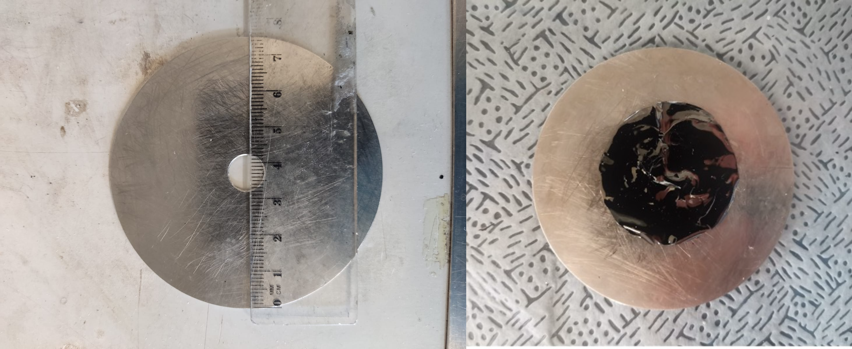
Before the permeation experiments, membranes are glued to a steel O-ring support with an epoxy glue (Araldite® Standard) – Figure 3.
After, the epoxy glue cured for approximately 6 hours and then membranes are placed inside the membrane cell – Figure 4. The entire system is then evacuated until a pressure of ca. 0.01 bar. After that, a feed pressure of 1 bar is fed to the cell.

The permeability of the membranes is computed from the time derivative of the permeating pressure. The permeability of a membrane, \( P_i \), is calculated from the equation:
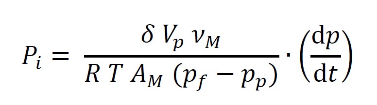
where \( \delta \) is the membrane thickness (determined with a high accuracy digital micrometer, Mitutoyo MDH-25M), \( V_p \) is the volume of the permeate tank, \( \nu_M \) is the molar volume of the gas at normal conditions, \( R \) is the universal gas constant, \( T \) is the absolute temperature, \( p_f \) and \( p_p \) are the feed and the permeate pressure, respectively, and \( t \) is the time.